JG-01
Embedded Firmware Technical Documentation
ESP32-S3 • Murata SCH16T • BLE • OTA • Real-Time Steering Control
| Document | Value |
| Document ID | JG01-FW-TD-001 |
| Revision | 1.1 |
| Source package | src(1).zip |
| Source date | July 2026 |
| Document date | 18 July 2026 |
| Status | Code-based technical description |
Revision History
| Revision | Date | Description |
| 1.0 | 18 July 2026 | Initial architecture skeleton. |
| 1.1 | 18 July 2026 | Expanded from full source-code review: organization, tasks, real-time processing, communications, settings, logging, and control behavior. |
Document Basis and Limitations
This document is derived from the supplied firmware source archive. It describes the implementation as found in the code rather than an intended future architecture. Where comments and executable values disagree, the executable value is treated as authoritative and the discrepancy is called out explicitly.
Table of Contents
1. Introduction
2. Firmware Organization
3. System Architecture
4. Startup and Initialization
5. Real-Time Execution Model
6. Main Control Algorithm
7. Sensor Subsystem
8. Receiver Inputs
9. Servo Output and Dual-Servo Mixing
10. Settings, Profiles, and Persistence
11. BLE, JSON API, and OTA
12. Web/Settings Runtime
13. Logging Subsystem
14. LED and Operator Feedback
15. Concurrency and Shared State
16. Module Reference
17. Design Assessment and Observations
Appendix A. Parameter Catalogue
Appendix B. JSON Command Catalogue
Appendix C. Pin and Timing Summary
1. Introduction
1.1 Purpose
The JG-01 firmware implements a steering-assistance controller for a rear-wheel-drive RC drift vehicle. It acquires steering, gain, and throttle commands from the radio receiver; measures vehicle yaw rate and acceleration using a Murata SCH16T inertial sensor; calculates a corrective steering component; and drives one or two steering servos. The same firmware also provides configuration, profile storage, BLE communication, firmware update, web/settings functions, diagnostics, and SD-card logging.
1.2 Scope
Source-code structure and module responsibilities.
ESP32-S3 startup, FreeRTOS tasks, interrupt timing, and core assignment.
The complete 400 Hz control-cycle data path.
IMU, receiver, servo, profile, BLE, OTA, settings, and logging behavior.
Concurrency controls and implementation observations relevant to maintenance.
1.3 Key implementation facts
| Item | Implementation |
| Controller | ESP32-S3 using Arduino framework and FreeRTOS |
| Primary sensor | Murata SCH16T-K01 over SPI |
| Control period | 2,500 µs, corresponding to 400 Hz |
| Receiver inputs | Three PWM inputs or FlySky iBus |
| Outputs | One standard servo output or two independently mapped outputs |
| Configuration | BLE JSON API and settings/web subsystem |
| Persistence | ESP32 Preferences/NVS with four profiles |
| Firmware update | BLE OTA and web OTA support |
| Logging | Binary samples buffered through a FreeRTOS queue to SD card |
2. Firmware Organization
The project is organized as one main Arduino sketch plus focused C++ modules. The main sketch owns the physical control path and top-level state. Supporting modules encapsulate sensor access, configuration transport, parameter validation, filtering, drift detection, return damping, receiver decoding, and logging.
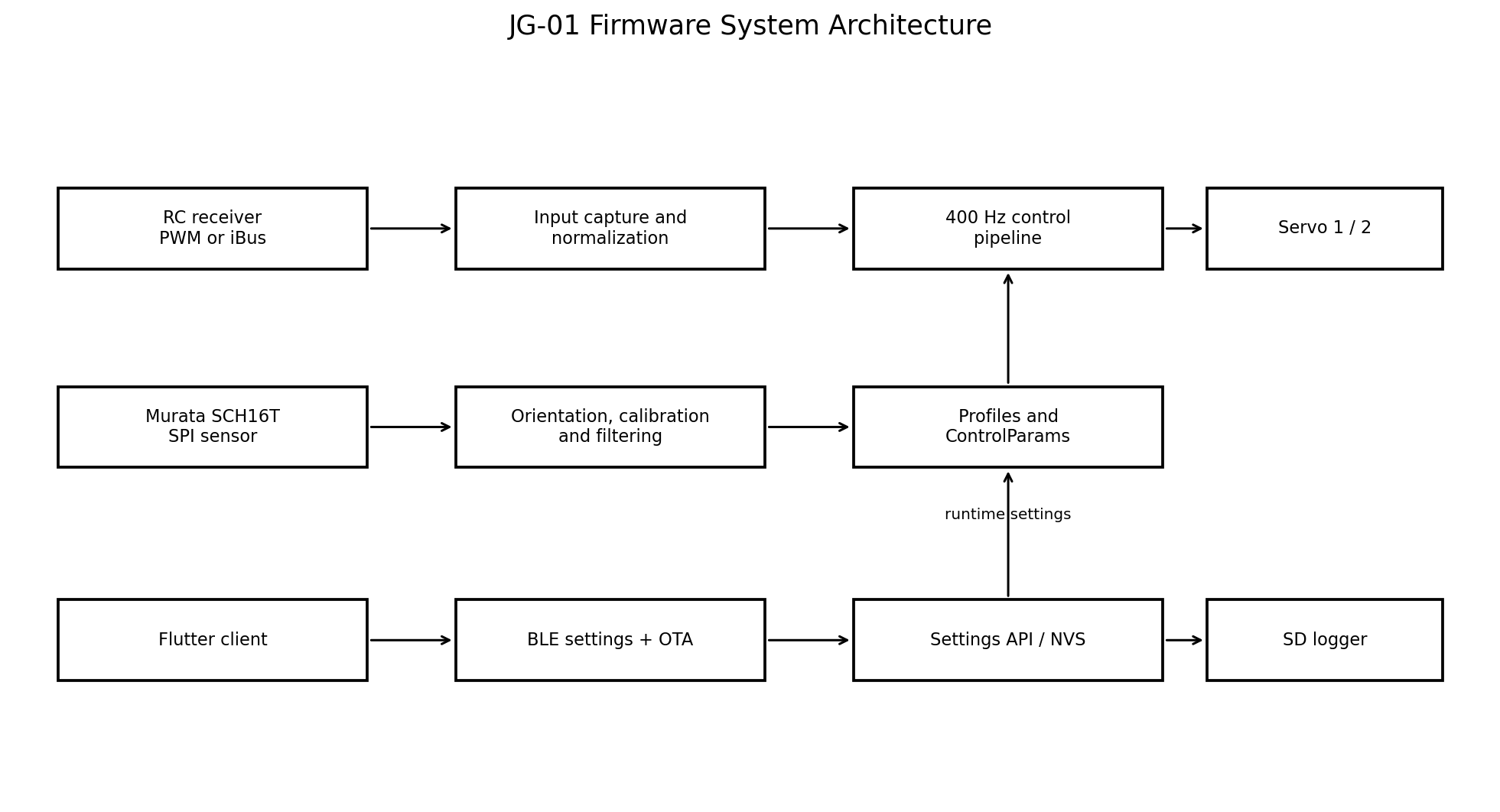
Figure 1. Major firmware subsystems and their data relationships.
2.1 Source groups
| Group | Principal files | Responsibility |
| Main runtime | rc_drift_gyro_01.ino | Pins, global runtime objects, startup, timer ISR, FreeRTOS tasks, control algorithm, servo writes, and profile switching. |
| Sensor driver | SCH16T.cpp/.h | Register-level SCH16T initialization, diagnostics, raw data acquisition, conversion, filters, sensitivities, and serial number. |
| Settings and UI | settings.cpp/.h | Web/settings pages, Preferences access, profiles, EPA, dual-servo configuration, logging controls, web OTA, and websocket data. |
| Transport/API | BluetoothSettingsTransport.*, SettingsApi.*, SettingsService.* | BLE GATT service, authentication, JSON command dispatch, OTA transaction, validation, and generic parameter access. |
| Control helpers | lpfilter.*, derivative.*, DerivativeN.h, driftdetector.*, ReturnDamping.*, RollingPeak.*, rolling_max_float.h, notchFilter.*, WobbleDetectorZC.h, AdaptiveGains.h | Signal filtering, derivatives, drift classification, damping, rolling peaks, and experimental/available control utilities. |
| Receiver | IbusReceiver.* | UART initialization, 32-byte frame collection, checksum validation, channel extraction, and diagnostics. |
| Logging | logging.* | SD initialization, queue-based sample transfer, buffering, periodic flush, shutdown, and dropped-sample count. |
| Parameters | ControlParams.h, params_list.h | Single-source parameter definitions, defaults, typed storage, and runtime lookup. |
| Build metadata | generated_version.h | Firmware version, Git revision, branch, dirty flag, and build timestamp. |
2.2 Main-sketch ownership
The main sketch is deliberately central. It creates the SCH16T object, servo objects, filters, detectors, task handles, hardware timer, receiver pulse state, live telemetry, profile state, and the active ControlParams instance. This makes the time-critical path easy to follow, but it also means rc_drift_gyro_01.ino is the primary integration point and carries substantial global state.
3. System Architecture
The firmware separates the high-rate steering loop from lower-rate management work. Core 1 is reserved for the timer-triggered control task. Core 0 runs status indication and the communications/settings task. Logging creates an additional task on a caller-selected core when recording begins.
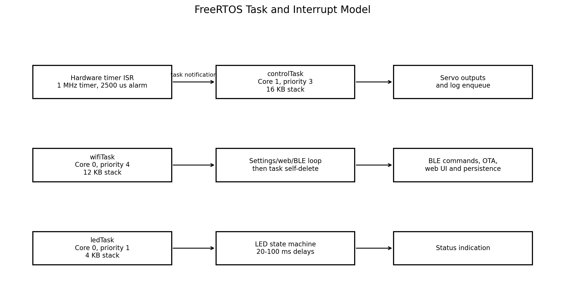
Figure 2. FreeRTOS tasks, core placement, priorities, and principal responsibilities.
3.1 Data path
Receiver signals are captured either by GPIO edge interrupts or by iBus UART parsing.
The control task wakes from a hardware-timer notification every 2.5 ms.
The task snapshots current settings, reads inputs, and normalizes steering and throttle.
SCH16T data is acquired and transformed into the selected installation orientation.
Yaw-rate and acceleration signals pass through configurable filters and derivative processing.
The P+D control calculation is shaped by drift detection, steering priority, correction exponent, lateral-acceleration assistance, peak holding, low-pass filtering, and a delta limiter.
The correction is added to driver steering, constrained by EPA, filtered, optionally mapped to two servos, and written as PWM.
Every fourth control cycle a telemetry record is offered to the logging queue.
4. Startup and Initialization
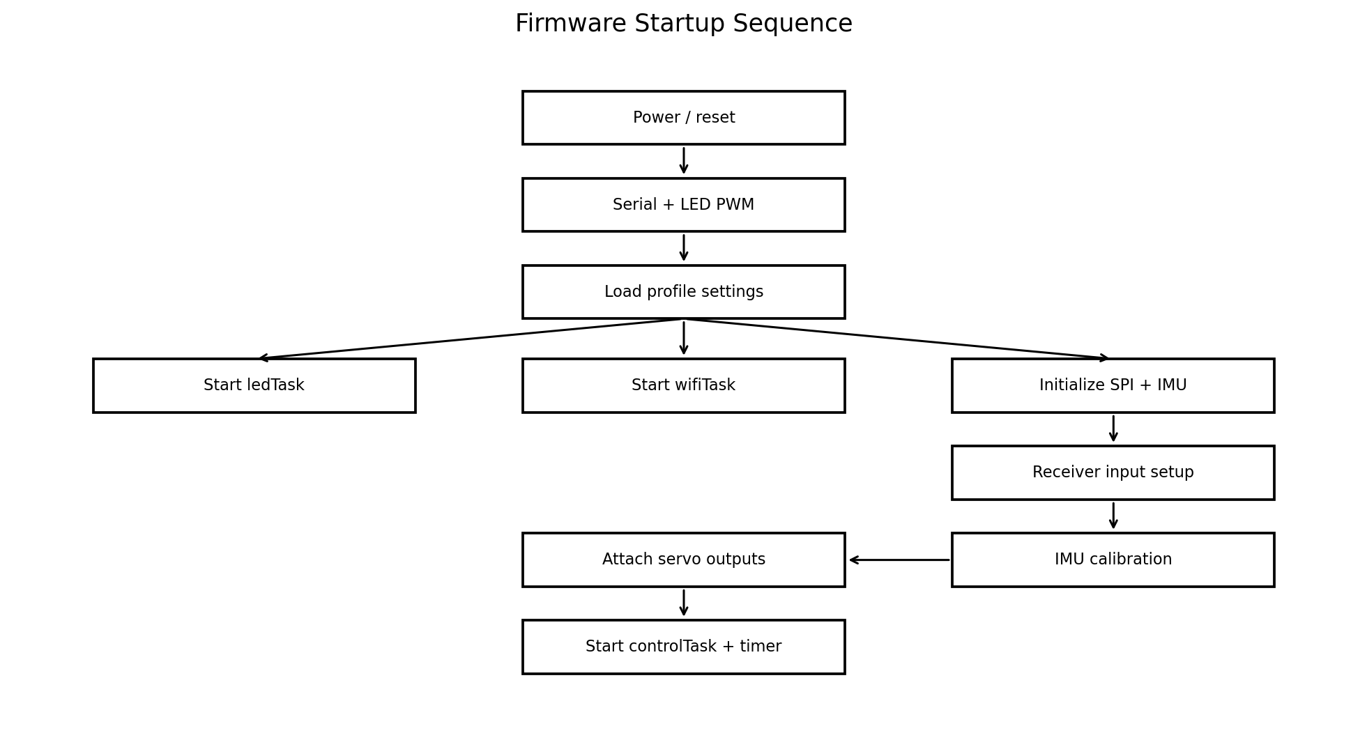
Figure 3. Startup order implemented in setup().
4.1 Startup order
Start the serial port at 115200 baud and select slow LED blinking.
Initialize LED PWM immediately, then load stored settings.
Create ledTask on core 0 at priority 1.
Create wifiTask on core 0 at priority 4 before IMU startup. This intentionally keeps settings and OTA access available even if the IMU is absent or calibration fails.
Start SPI and configure SCH16T filter, sensitivity, and decimation structures from the loaded settings.
Attempt IMU initialization for up to 2 seconds. If initialization fails, setup() returns without starting the control task. Communications remain available because wifiTask is already running.
Initialize either iBus or three GPIO pulse inputs.
Run IMU calibration with a 5-second timeout. The control task is still permitted to start if calibration does not complete.
Configure two servo objects with 14-bit timer width and the validated servo frequency.
Reload settings, create controlTask on core 1, and start the periodic hardware timer.
Set LED brightness and indicate whether the base or secondary runtime profile is active.
4.2 Fault behavior during startup
| Condition | Behavior |
| IMU initialization failure | The high-rate control task is not created. BLE/settings/OTA remain available, and the LED continues slow blinking. |
| IMU calibration failure | A warning is printed; control starts without newly calculated offsets. |
| Receiver mode iBus | UART-based iBus is initialized and channels 1, 3, and 4 are used. |
| Receiver mode PWM | CHANGE interrupts are attached to steering, gain, and throttle GPIOs. |
5. Real-Time Execution Model
5.1 Hardware timer and task notification
Timer 0 is configured with an 80:1 prescaler, producing a 1 MHz timer tick. Its auto-reload alarm is set to LOOP_PERIOD_US = 2500. The interrupt service routine calls vTaskNotifyGiveFromISR() for controlTask and requests a context switch when necessary. The task blocks indefinitely in ulTaskNotifyTake() and therefore consumes no CPU while waiting.
The executable period is 2.5 ms, or 400 Hz. A nearby source comment says “5 ms = 200 Hzâ€; that comment is stale and does not match the constant or timer configuration.
5.2 Task inventory
| Execution context | Core | Priority | Stack | Scheduling |
| Timer ISR | Interrupt | Hardware level | N/A | Every 2,500 µs; sends direct task notification. |
| controlTask | 1 | 3 | 16,384 bytes | Event-driven by timer notification; runs one complete control cycle per wake-up. |
| wifiTask | 0 | 4 | 12,288 bytes | Calls setupSettings(), then repeatedly calls makeSettings() with a 50 ms delay while it returns true; deletes itself when finished. |
| ledTask | 0 | 1 | 4,096 bytes | Permanent state machine; delay is 20 or 100 ms depending on mode. |
| LoggerTask | Configured by caller | 3 | 16,384 bytes | Created only while logging is active; blocks on queue receive and periodically flushes SD writes. |
| GPIO receiver ISRs | Interrupt | Hardware level | N/A | Capture rising/falling edges and update pulse-width snapshots. |
5.3 Timing behavior
The control task calculates measured dt from micros() for manual dual-servo ramping, while filter/derivative objects also use the configured nominal loop period in several places.
No blocking delay appears in the main control cycle. SD writes are delegated through a non-blocking queue.
Serial debug printing is rate limited to approximately 5 Hz and additionally suppressed when receiver input activity is recent, reducing interference with pulse capture.
The Arduino loop() is intentionally idle and sleeps for one second; application work is task-driven.
5.4 Overrun considerations
A direct task notification acts as a counting semaphore. If a control iteration exceeds 2.5 ms, notifications can accumulate, but the task has no explicit deadline-miss counter or execution-time monitor. Consequently, a sustained overrun may cause back-to-back iterations instead of preserving evenly spaced control updates. Instrumenting cycle duration and notification backlog would improve observability.
6. Main Control Algorithm
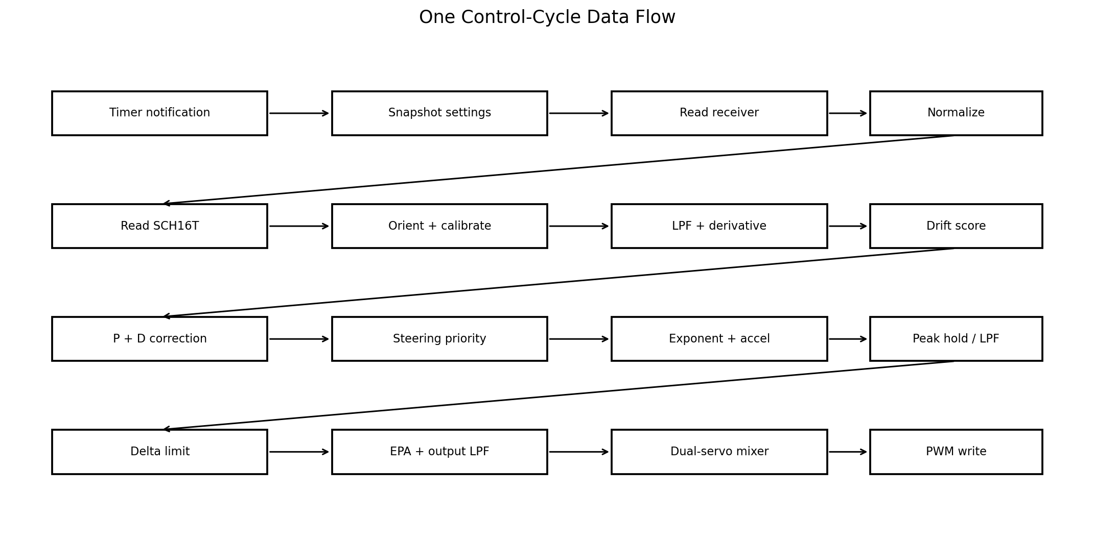
Figure 4. Processing sequence performed by each controlTask iteration.
6.1 Settings synchronization
When settings_changed is set, the control task reloads the active profile. It then copies the global ControlParams object into a local stack variable while holding cp_mux. The local snapshot prevents individual fields from changing midway through a cycle. Profile-switch logic may update the runtime profile, after which the task snapshots ControlParams again.
6.2 Receiver acquisition and normalization
PWM mode reads volatile pulse-width snapshots under s_mux. iBus mode calls ibusUpdate() and maps channel 1 to steering, channel 3 to gain, and channel 4 to throttle. Steering can be reversed around the stored EPA center. Gain is mapped from nominal 1000-2000 µs into 0.0-1.0. Steering and throttle are low-pass filtered and normalized through SteeringMap objects.
6.3 IMU processing
The task requests raw SCH16T data and converts it into engineering units. applyImuOrientation() supports eight installation orientations by swapping and negating body axes. Body Z angular rate becomes gyrodps. Body X acceleration, after removal of the lateral setpoint, becomes the lateral-acceleration assistance input.
6.4 Yaw-rate P+D correction
Yaw rate is low-pass filtered to form the proportional signal. A derivative object calculates yaw acceleration and a second low-pass filter suppresses derivative noise. The core correction is:
gyro_correction = drift_multiplier × configured_gain × receiver_gain × (pid_p × filtered_yaw_rate + pid_d × filtered_yaw_derivative)
No integral term is used. This is consistent with a drift-assistance controller where the desired behavior is rate-sensitive support rather than elimination of a persistent heading error.
6.5 Drift-dependent gain
DriftDetector receives normalized steering, filtered yaw rate, and configured gain. Its output is converted into a multiplier of 1 + (drift_value / 10) × dd_multiplier. The intention is to increase correction when steering/yaw conditions indicate an established drift.
6.6 Steering priority
The derivative of normalized driver steering reduces gyro authority during rapid manual steering movement. The correction is divided by 1 + (|steering derivative| / 2) × steering_prio. This preserves driver authority during transitions and fast counter-steering inputs.
6.7 Nonlinear shaping and acceleration assistance
correction_exp applies a sign-preserving power function normalized around a correction magnitude of 150. Values above one suppress small corrections relative to large ones; values below one do the opposite. Filtered lateral acceleration is multiplied by acc_lat_multip, clamped to ±50 µs, and added to the gyro correction.
6.8 Peak hold, filtering, and slew limiting
RollingMaxCorr stores a recent maximum-magnitude correction. For the first 60% of the configured rollmaxcorr age window, that peak is held. During the remaining 40%, the output blends back toward the current correction. A correction low-pass filter follows. Finally, max_d_corr constrains the change relative to the previous cycle, acting as a global correction slew limiter.
6.9 Output construction
The final correction is added to the filtered receiver steering pulse. When EPA is enabled, the result is clamped to the stored low/high endpoints. A servo-output low-pass filter is applied before normal or dual-servo output mapping. A deadband-like condition attempts to retain the previous output when the change is below 2 µs; however, it appears before the new out value is calculated and should be reviewed because its effective behavior may not match the apparent intent.
6.10 Logging cadence
logging_counter causes one sample to be enqueued every fourth control iteration. At a 400 Hz control rate this gives a nominal logging rate of 100 Hz. The record includes filtered and raw gyro values, correction, input/output pulses, gain input, normalized throttle, receiver gain, and three raw acceleration axes.
7. Sensor Subsystem
7.1 SCH16T configuration
| Property | Value / source |
| SPI chip select | GPIO 10 |
| Reset | Not connected in software (−1) |
| Rate sensitivity | 3200 LSB/(°/s) for Rate1 and Rate2 |
| Acceleration sensitivity | 3200 LSB/(m/s²) for Acc1, Acc2, and Acc3 |
| Rate2 decimation | 4 |
| Acc2 decimation | 4 |
| Filter settings | Loaded from imu_r_filt_hz, imu_a12_filt_hz, and imu_a3_filt_hz; defaults are 68 Hz |
| Runtime signals used | Rate1 Z for yaw; Acc1 X/Y/Z for acceleration and logging |
7.2 Initialization and diagnostics
initializeImu() repeatedly calls imu.begin() until success or timeout. The SCH16T driver is significantly larger than the control modules and contains register-level startup, status checks, filter/sensitivity configuration, conversion, and device-identification logic. After initialization the firmware reads and prints the sensor serial number.
7.3 Calibration and orientation
Calibration establishes acceleration offsets and a lateral acceleration setpoint while the car is stationary. Eight orientation modes allow the PCB to be installed in multiple rotations and inverted configurations without rewriting the control algorithm. The orientation mapping is applied consistently before yaw and body acceleration are used.
8. Receiver Inputs
8.1 PWM mode
Steering, gain, and throttle use GPIO 3, 4, and 39. CHANGE interrupts measure high-pulse duration. Shared pulse variables are volatile and copied under s_mux in the control task. This keeps ISR work minimal and avoids disabling interrupts for longer than the snapshot operation.
8.2 iBus mode
IbusReceiver reads fixed 32-byte frames, validates the protocol checksum, extracts channel values, and maintains diagnostics including valid-frame count, checksum errors, frame errors, last-frame time, and raw-frame bytes. The normal control calculations are unchanged after channel values are selected.
8.3 Runtime profile switching
Each base profile can define a secondary profile and an iBus switch channel. The control loop evaluates the selected channel with a 100 ms debounce period and loads either the base or secondary runtime profile. The LED uses a distinct pattern while the secondary profile is active.
9. Servo Output and Dual-Servo Mixing
9.1 Servo generation
ESP32Servo is configured with 14-bit timer width. GPIO 5 drives servo 1 and GPIO 6 drives servo 2. servo_hz is validated before use; its default is 200 Hz. In single-servo mode only servo 1 is updated by the control task.
9.2 Nine-point mapping
Dual-servo mode uses nine steering input points at −100, −80, −50, −20, 0, 20, 50, 80, and 100 percent. Independent left and right tables are linearly interpolated between adjacent points. Negative and positive sides are scaled relative to their respective endpoint magnitudes. Servo 2 uses the right-side curve and then reverses sign so the two physical steering actuators can work in opposition.
9.3 Manual test mode
The settings interface can take temporary control of the servos for calibration. The requested test input is ramped at 500 µs/s using the measured cycle dt, preventing an abrupt jump. Release-to-center ramps back to 1500 µs and automatically returns ownership to the normal control path after center is reached.
10. Settings, Profiles, and Persistence
10.1 Parameter model
params_list.h is an X-macro list and is the single place where regular ControlParams fields and defaults are declared. ControlParams.h includes the list three times to initialize defaults, build a name-to-pointer table, and declare typed members. This reduces duplication and lets the SettingsService access parameters by name.
10.2 Four-profile storage
The firmware supports four profiles. Each profile uses its own Preferences namespace (rc0 through rc3), while legacy values can be read from an older rc namespace. The active base profile, profile names, secondary profile, switch channel, EPA values, dual-servo map, and common settings are loaded and saved through settings.cpp and companion routines in the main sketch.
10.3 Runtime change model
SettingsService validates incoming text, writes the typed value into ControlParams, and marks settings_changed. The control task observes that flag and reloads its active settings. The cp_mux critical section protects snapshots and settings-sensitive shared values. Persistent commands save values to Preferences; temporary set operations can modify runtime behavior without necessarily committing it.
10.4 Validation
Murata filter values are restricted to supported rates.
Servo frequency is checked by isValidServoHz()/validatedServoHz().
Known parameters are parsed by type and rejected with an error string when invalid.
BLE authentication is enforced when device_pwd is non-empty.
11. BLE, JSON API, and OTA
11.1 GATT service
| Characteristic | Properties | Purpose |
| Settings TX | Read + Notify | JSON replies and asynchronous text notifications. |
| Settings RX | Write + Write Without Response | JSON settings commands from the client. |
| OTA Control | Write + Write Without Response | ota_begin, ota_status, ota_end, and ota_abort transaction control. |
| OTA Data | Write + Write Without Response | Raw firmware binary chunks. |
The peripheral advertises a custom settings service, uses an MTU of 185, high transmit power, and conservative 40-80 ms advertising intervals intended to improve compatibility with Windows/WinRT adapters.
11.2 Request handling
BLE write callbacks do not execute the complete command directly. They store a pending request, and BluetoothSettingsTransport::loop() later removes and processes it. Authentication is handled before SettingsApi dispatch. Responses are serialized as JSON and sent by notification.
11.3 JSON command groups
| Group | Commands |
| Information and parameters | get_info, list_params, get_param, set_param, set_param_save, set_params, save_params |
| Profiles | get_profiles, get_profileinfo, load_profile, set_profile_name, set_profile_switch, copy_profile |
| Logging | get_logging, start_logging, stop_logging |
| EPA | enter_epa, exit_epa, get_epa, capture_epa, save_epa |
| Dual servo | get_dual_servo, set_dual_servo, set_dual_servo_options, dual_servo_go, dual_servo_live, dual_servo_center/release, save_dual_servo |
11.4 BLE OTA transaction
ota_begin validates the declared image size and opens an ESP32 Update transaction. OTA Data writes raw bytes and tracks the number accepted. ota_status reports progress. ota_end verifies the completed image and schedules reboot. ota_abort terminates an active transaction. Progress notifications are intentionally not interleaved with the high-rate data callback because some Windows BLE stacks fail when notifications and firmware writes overlap.
11.5 Build identification
get_info returns firmware version, Git commit, branch, dirty-build flag, build date/time, and BLE device name. This makes field units traceable to the exact software build used.
12. Web/Settings Runtime
settings.cpp contains the browser-facing management implementation. It builds HTML pages, websocket telemetry, profile controls, logging pages, firmware-upload handlers, file download, EPA functions, dual-servo setup, Wi-Fi persistence, and settings save operations. setupSettings() initializes the subsystem; makeSettings() services it from wifiTask at approximately 20 Hz due to the 50 ms task delay.
12.1 Separation from the control loop
The communications/settings task is pinned to core 0, while the control task is pinned to core 1. This reduces the risk that HTTP, BLE, HTML construction, flash writes, or OTA processing directly delay the 400 Hz steering loop. Shared state is exchanged through snapshots, flags, and critical sections rather than by invoking browser logic from the control task.
12.2 EPA mode
EPA mode exposes live receiver pulses, captures low/center/high steering and throttle points, saves them to non-volatile storage, and can temporarily disable normal endpoint limiting. The LED blinks fast while endpoint protection is disabled, providing a visible warning.
13. Logging Subsystem
13.1 Producer-consumer design
The control task is the producer and never writes the SD card directly. loggingEnqueue() calls xQueueSend() with zero wait. If the queue is full, the sample is dropped and a counter is incremented rather than blocking control execution. LoggerTask is the consumer and performs buffered writes and file flushes.
13.2 Structures and buffering
| Item | Value |
| Queue length | 256 LogSample records |
| Record payload | uint32 timestamp plus eleven float channels |
| Write buffer | 11 samples |
| Nominal producer rate | 100 Hz (every fourth 400 Hz cycle) |
| Logger priority | 3 |
| Logger stack | 16,384 bytes |
| Stop timeout | 2 seconds while waiting for task exit |
13.3 Logged channels
| Field | Control-loop value |
| t_us | Elapsed logging time divided by 1000; despite the name, stored unit is milliseconds. |
| p1 | Filtered yaw rate |
| p2 | Raw converted yaw rate |
| p3 | Final gyro correction |
| p4 | Filtered steering input pulse |
| p5 | Combined steering output before dual-servo mapping |
| p6 | Raw gain input pulse |
| p7 | Normalized throttle |
| p8 | Mapped receiver gain 0-1 |
| p9-p11 | Raw converted Acc1 X, Y, and Z values |
The timestamp member name t_us is misleading because the assignment divides microseconds by 1000. Documentation and downstream log readers should treat it as elapsed milliseconds unless the source is changed.
14. LED and Operator Feedback
ledTask is an independent low-priority state machine using ESP32 LEDC PWM. LED_OFF and LED_ON update every 100 ms. Fast blink uses a 200 ms full period; slow blink uses 800 ms. Secondary-profile mode stays on for 800 ms and off for 200 ms. Brightness and command are copied under led_mux.
| LED state | Meaning in current implementation |
| Slow blink | Startup or IMU initialization failure; management interfaces remain available. |
| On | Base profile active and normal operation. |
| Secondary pattern | Runtime secondary profile active. |
| Fast blink | EPA limiting disabled / calibration-related warning state. |
| Off | Explicit status command. |
15. Concurrency and Shared State
15.1 Critical sections
| Lock | Protected data / use |
| s_mux | PWM receiver pulse snapshots and ISR-updated values. |
| cp_mux | ControlParams snapshots and selected control/settings flags. |
| dual_servo_manual_mux | Manual test ownership, target, current position, and release state. |
| led_mux | LED command and brightness. |
| Interrupt disable in BLE transport | Pending String request handoff between callback and transport loop. |
15.2 Communication patterns
Direct-to-task notification: timer ISR to controlTask.
Queue: controlTask to LoggerTask.
Volatile snapshots + critical sections: receiver ISRs to controlTask.
Flag + reload: SettingsService to controlTask.
Pending request buffer: BLE callback to transport loop.
Local copy of ControlParams: stable settings for each high-rate cycle.
15.3 Risks to review
String operations and noInterrupts()/interrupts() in the BLE pending-request handoff should remain short; a queue would provide a more explicit thread-safe boundary.
settings_changed is a shared flag; making it atomic or consistently protecting it would clarify memory ordering.
Some control code uses cp directly instead of cp_local, notably drift calculation fields, which can undermine the otherwise careful per-cycle snapshot model.
There is no explicit watchdog, control-cycle deadline monitor, or receiver failsafe behavior described in the supplied main path.
LoggerTask and controlTask both use priority 3. Core selection for logging should avoid competing with control on core 1.
16. Module Reference
| Module | Role |
| rc_drift_gyro_01.ino | Top-level integration: pins, settings/profile loading, receiver ISRs, IMU initialization/calibration, FreeRTOS task creation, timer ISR, LED task, dual-servo mixer, and 400 Hz control loop. |
| SCH16T.cpp/.h | Murata sensor driver with device startup, register transactions, diagnostic validation, raw acquisition, unit conversion, filter/sensitivity/decimation setup, and serial-number access. |
| BluetoothSettingsTransport.cpp/.h | BLE server, advertised name, authentication, request buffering, response notification, four GATT characteristics, and transactional BLE OTA. |
| SettingsApi.cpp/.h | JSON command router and response construction for information, parameters, profiles, logging, EPA, and dual-servo functions. |
| SettingsService.cpp/.h | Typed parameter read/write adapter, value validation, and settings-change notification. |
| settings.cpp/.h | Web/UI service, NVS persistence, profile administration, websocket handling, SD/log controls, web OTA, EPA and dual-servo settings. |
| ControlParams.h + params_list.h | Compile-time construction of typed parameter storage and defaults from a single X-macro list. |
| IbusReceiver.cpp/.h | Non-blocking iBus frame parser, checksum verification, 14-channel extraction, and debug counters. |
| logging.cpp/.h | Asynchronous SD logger using a FreeRTOS queue and dedicated task. |
| lpfilter.cpp/.h | First-order low-pass filter with configurable cutoff and loop time. |
| derivative.cpp/.h + DerivativeN.h | Single-step and multi-sample derivative estimators. |
| driftdetector.cpp/.h | Computes a drift likelihood/value from steering and yaw-rate conditions. |
| ReturnDamping.cpp/.h | Calculates damping behavior intended to control correction return. |
| RollingPeak.cpp/.h + rolling_max_float.h | Recent peak and age tracking used for correction holding/fading. |
| notchFilter.cpp, WobbleDetectorZC.h, AdaptiveGains.h | Additional oscillation-detection, notch, and adaptive-gain utilities; some are instantiated or available but not central to the active correction path in this revision. |
| SteeringMap.h | Maps pulse widths to normalized steering/throttle values using stored endpoints. |
17. Design Assessment and Observations
17.1 Strengths
The control task is isolated on core 1 and triggered by a hardware timer rather than Arduino loop timing.
Control-cycle SD work is non-blocking and queue based.
Management/OTA is started before the IMU, allowing recovery from a sensor fault.
Settings are snapshotted for deterministic per-cycle use.
Receiver abstraction allows PWM and iBus without changing downstream control logic.
BLE separates JSON control traffic from raw OTA data.
Profiles, secondary-profile switching, EPA, and dual-servo mapping are integrated into the runtime rather than bolted onto the mobile app.
Build metadata and dropped-log-sample counters support field diagnostics.
17.2 Important code observations
| Observation | Impact / recommendation |
| LOOP_PERIOD_US is 2500 while its comment says 5 ms / 200 Hz. | Actual rate is 400 Hz. Correct the comment to avoid tuning and documentation errors. |
| LogSample.t_us stores (micros-start)/1000. | Value is milliseconds. Rename to t_ms or store true microseconds. |
| Small-output hold test occurs before out is recalculated. | Review ordering to verify intended servo deadband behavior. |
| return_damping is calculated but not visibly applied to corr in the active path. | Either integrate the value or remove dead code to avoid false assumptions. |
| cp_local is used for many settings, but some expressions reference global cp. | Use one immutable cycle snapshot consistently. |
| No deadline/overrun counter. | Measure cycle execution time and missed timer notifications. |
| No obvious input timeout/failsafe in the reviewed control path. | Define behavior for stale PWM/iBus frames and invalid pulse values. |
| Main sketch contains extensive global state. | Future refactoring could isolate ReceiverService, ControlLoop, ImuService, ServoService, and ProfileManager without changing behavior. |
17.3 Recommended verification tests
Measure controlTask execution-time distribution at 400 Hz with BLE active, web UI active, and logging active.
Verify receiver loss behavior separately for PWM and iBus.
Confirm correction sign for all eight IMU orientation modes.
Sweep yaw-rate and steering inputs to validate steering-priority and nonlinear exponent behavior.
Test rollmaxcorr peak hold and fade at boundary values 0, 1, and typical window sizes.
Verify servo update frequency and pulse timing for both single- and dual-servo operation.
Stress BLE OTA on Windows, Android, and iOS while monitoring control-task timing.
Fill the logging queue deliberately and verify dropped-sample reporting and safe stop.
Appendix A. Parameter Catalogue
| Name | Type | Default | Purpose |
| gain | float | 0.0 | Master configured gyro gain. |
| gyro_avg | int | 0 | Legacy/available gyro averaging control. |
| steering_prio | float | 0.0 | Reduces gyro correction during fast driver steering. |
| debug_serial | int | 0 | Enables rate-limited serial control diagnostics. |
| correction_exp | float | 1.0 | Nonlinear correction exponent. |
| gyro_lp_hz | int | 20 | Yaw-rate low-pass cutoff. |
| derivative_lp_hz | int | 20 | Yaw derivative low-pass cutoff. |
| steer_in_lp_hz | int | 20 | Receiver steering low-pass cutoff. |
| steer_out_lp_hz | int | 20 | Servo command low-pass cutoff. |
| pid_p | float | 5.0 | Yaw-rate proportional coefficient. |
| pid_d | float | 1.0 | Yaw-acceleration derivative coefficient. |
| wobble_det_a | float | 0.2 | Wobble detector parameter. |
| dd_min_steer | float | 0.05 | Minimum steering magnitude for drift detection. |
| dd_min_yaw | float | 10 | Minimum yaw rate for drift detection. |
| dd_multiplier | float | 1 | Drift-dependent gain multiplier. |
| max_d_corr | float | 0.05 | Maximum correction change per cycle. |
| corr_lp_hz | float | 5.0 | Final correction low-pass cutoff. |
| acc_lat_multip | float | 10 | Lateral acceleration assistance gain. |
| imu_orientation | int | 0 | One of eight sensor mounting transformations. |
| imu_r_filt_hz | int | 68 | SCH16T rate filter selection. |
| imu_a12_filt_hz | int | 68 | SCH16T Acc1/2 filter selection. |
| imu_a3_filt_hz | int | 68 | SCH16T Acc3 filter selection. |
| rollmaxcorr | int | 10 | Rolling correction peak-hold/fade window. |
| dual_servo_enabled | int | 0 | Enables two-servo output mapping. |
| receiver_input_mode | int | 0 | 0 = PWM, 1 = iBus. |
| servo_hz | int | 200 | Servo PWM refresh frequency. |
| profile_secondary | int | 1 | Secondary profile index. |
| profile_switch_channel | int | 0 | iBus channel used for profile switching. |
| device_ssid | string | JASAGYRO-01 | Device network/advertised configuration name. |
| device_pwd | string | 12345678 | Configuration/BLE authentication password. |
Appendix B. JSON Command Catalogue
| Command | Purpose |
| get_info | Read build and BLE identity. |
| list_params | Return all parameter metadata and values. |
| get_param | Read one parameter by name. |
| set_param | Change one runtime parameter. |
| set_param_save | Change and persist one parameter. |
| set_params | Change multiple parameters. |
| save_params | Persist current parameter set. |
| get_profiles / get_profileinfo | Read profile names and selection metadata. |
| load_profile | Select and load a profile. |
| set_profile_name | Rename a profile. |
| set_profile_switch | Set secondary profile and switch channel. |
| copy_profile | Copy active profile to another slot. |
| get_logging / start_logging / stop_logging | Inspect and control SD logging. |
| enter_epa / exit_epa / get_epa | Manage EPA calibration mode. |
| capture_epa / save_epa | Capture and persist endpoint values. |
| get_dual_servo | Read map, options, and live values. |
| set_dual_servo | Stage/apply full nine-point map. |
| set_dual_servo_options | Immediately update enable/reverse options. |
| dual_servo_go / dual_servo_live | Temporary calibration positioning. |
| dual_servo_center | Center and release manual test. |
| save_dual_servo | Persist the dual-servo configuration. |
| ota_begin / ota_status / ota_end / ota_abort | BLE firmware-update transaction control. |
Appendix C. Pin and Timing Summary
| Signal | GPIO / value |
| Steering PWM input | 3 |
| Gain PWM input | 4 |
| Throttle PWM input | 39 |
| Servo 1 output | 5 |
| Servo 2 output | 6 |
| Status LED | 7 / PIN_LED_CTRL in active LED implementation |
| SCH16T chip select | 10 |
| Control timer period | 2,500 µs |
| Control frequency | 400 Hz |
| Nominal log frequency | 100 Hz |
| Profile-switch debounce | 100 ms |
| Manual servo test ramp | 500 µs/s |
| BLE local MTU | 185 |
| BLE advertising interval | 40-80 ms |