Flutter Application Technical Documentation
Revision 1.2
18 July 2026
Revision History
| Revision | Date | Description |
| 1.2 | 18 July 2026 | Added RC drifting and drift-gyro introduction, title page, revision history, and table of contents. Existing technical content and diagrams retained. |
Table of Contents
Introduction 4
JasaGyro Flutter Application - Technical Documentation 5
Overview 5
1. Application Architecture 5
2. BLE Architecture 5
3. Connection Sequence 5
4. JSON Command Protocol 5
5. Parameter Management 6
6. OTA Firmware Update 6
7. Adaptive OTA Algorithm 6
8. Android Warm-up 6
9. Firmware Distribution 6
10. Design Assessment 7
11. Architecture Diagrams 7
12. Application Functions and Configuration Workflows 14
12.2 Parameter Read and Set Operation 16
12.3 EPA Settings Operation 18
12.4 Dual Servo Settings Operation 20
12.5 Concurrency, Response Matching, and Failure Handling 22
Introduction
Radio-controlled (RC) drifting is a specialized branch of RC motorsport in which a rear-wheel-drive vehicle is intentionally driven in a controlled oversteer condition. Unlike conventional racing, the objective is not simply to maximize cornering grip or lap speed, but to maintain a stable and controllable drift angle while following the desired line. Modern RC drift cars use large steering angles, specialized low-grip tires, carefully tuned suspension geometry, and fast digital steering servos.
Maintaining a stable drift requires continuous counter-steering. During rapid transitions or sudden changes in rear-tire grip, the required steering corrections may develop faster than the driver can react. Electronic steering gyroscopes are therefore widely used in rear-wheel-drive RC drift cars to improve stability and make the vehicle response more predictable.
A drift gyro measures the vehicle yaw rate with an angular-rate sensor and adds a corrective component to the driver’s steering command. Unlike a conventional heading-hold system, the gyro must not prevent the vehicle from rotating. It must support controlled rotation while preserving direct driver authority and a natural steering feel. Gyro gain, filtering, response speed, and correction limits strongly affect the behavior of the car.
Commercial drift gyros are available from manufacturers such as Yokomo, Reve D, Futaba, Sanwa, Power HD, and other RC electronics suppliers. These products are generally compact and effective, but their internal algorithms, filtering methods, and tuning strategies are proprietary.
The JG-01 project was created as a modern and extensible drift-gyro platform based on an ESP32-S3 microcontroller, a Murata inertial sensor, and a cross-platform Flutter application. The system is designed to support wireless configuration, diagnostics, profile management, Bluetooth Low Energy communication, and over-the-air firmware updates while providing a flexible foundation for continued control-algorithm development.
This document describes the Flutter application used to configure and maintain the JG-01 system. It covers the application architecture, BLE communication, command protocol, parameter handling, OTA firmware update process, configuration workflows, and relevant software design considerations.
JasaGyro Flutter Application Technical Documentation
Overview This document describes the architecture of the uploaded Flutter application for the JasaGyro BLE configuration utility. It is based on the provided source code and focuses on the communication architecture, OTA update process, BLE protocol, application flow, and software design.
1. Application Architecture
The application is structured around a single StatefulWidget (GyroSettingsPage) which currently contains most business logic. Startup sequence: • main() → runApp(JasaGyroApp) • MaterialApp creation • GyroSettingsPage initialization Responsibilities include BLE communication, authentication, parameter management, OTA updates, logging, profile management, EPA mode, dual-servo configuration and UI state.
2. BLE Architecture
The application exposes one custom BLE service with four major characteristics: • Settings RX (App→Device JSON commands) • Settings TX (Device→App notifications/replies) • OTA Control (OTA commands) • OTA Data (firmware stream) Normal commands are JSON encoded while firmware bytes are transferred separately for maximum throughput.
3. Connection Sequence
Scan → Connect → Discover Services → Enable Notifications → Authenticate → Download device information. The implementation includes retries, connection-state validation and platform-specific handling (especially Windows and Android).
4. JSON Command Protocol
Commands are serialized as JSON. Typical request: {"cmd":"get_info"} Responses complete a pending Future via a Completer, allowing synchronous-style command execution with timeout protection.
5. Parameter Management
Device parameters are cached locally. Modified parameters are collected separately and only changed values are written back using set_param_save before refreshing the parameter list.
6. OTA Firmware Update
OTA uses a two-channel architecture: Control: ota_begin ota_status ota_end ota_abort Data: Raw firmware binary chunks The application first negotiates chunk size, then streams firmware while tracking progress.
7. Adaptive OTA Algorithm
The OTA implementation dynamically adjusts transfer speed. Levels: Safe Normal Fast Turbo Every transfer window measures average write latency. If writes become slower the application automatically falls back to a safer mode. If communication remains fast it accelerates again.
8. Android Warm-up
The first few kilobytes are intentionally transferred using acknowledged 20-byte packets with long delays to avoid Android BLE GATT status 133 failures. After warm-up the transfer switches to write-without-response and larger packets.
9. Firmware Distribution
Firmware metadata is downloaded from: https://jasapart.com/jg01/firmware/latest.php The app compares versions, downloads the binary, validates size and immediately starts BLE OTA or optionally saves the firmware for WiFi OTA.
10. Design Assessment
Strengths: • Robust BLE connection handling • Adaptive OTA implementation • Clear command protocol • Automatic authentication • Good recovery from transient BLE failures Recommended future refactoring: • Split GyroSettingsPage into multiple files. • Create dedicated BLEService, OTAService, SettingsRepository and ProfileRepository. • Separate UI widgets from business logic. • Introduce immutable model classes. • Consider Provider/Riverpod/Bloc for state management. • Add unit tests for protocol serialization and OTA logic.
11. Architecture Diagrams
The following diagrams formalize the application structure and runtime behavior. They are intended for implementation review, maintenance, onboarding, and coordination with the ESP32 firmware developer.
11.1 System Context
The Flutter application acts as the central client. It communicates with the JG-01 over BLE, accesses the firmware distribution service over HTTPS, and stores selected local information such as the saved device password.
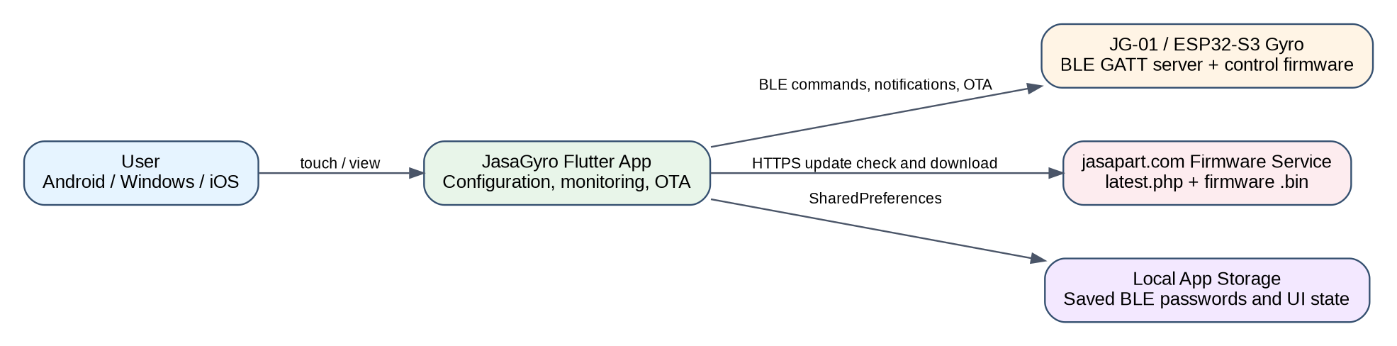
Figure 1. JasaGyro system context and external interfaces.
11.2 Flutter Application Component Architecture
The current implementation is functionally layered, although most responsibilities reside in one StatefulWidget. The diagram represents the logical separation that already exists and also provides a natural target for future refactoring.
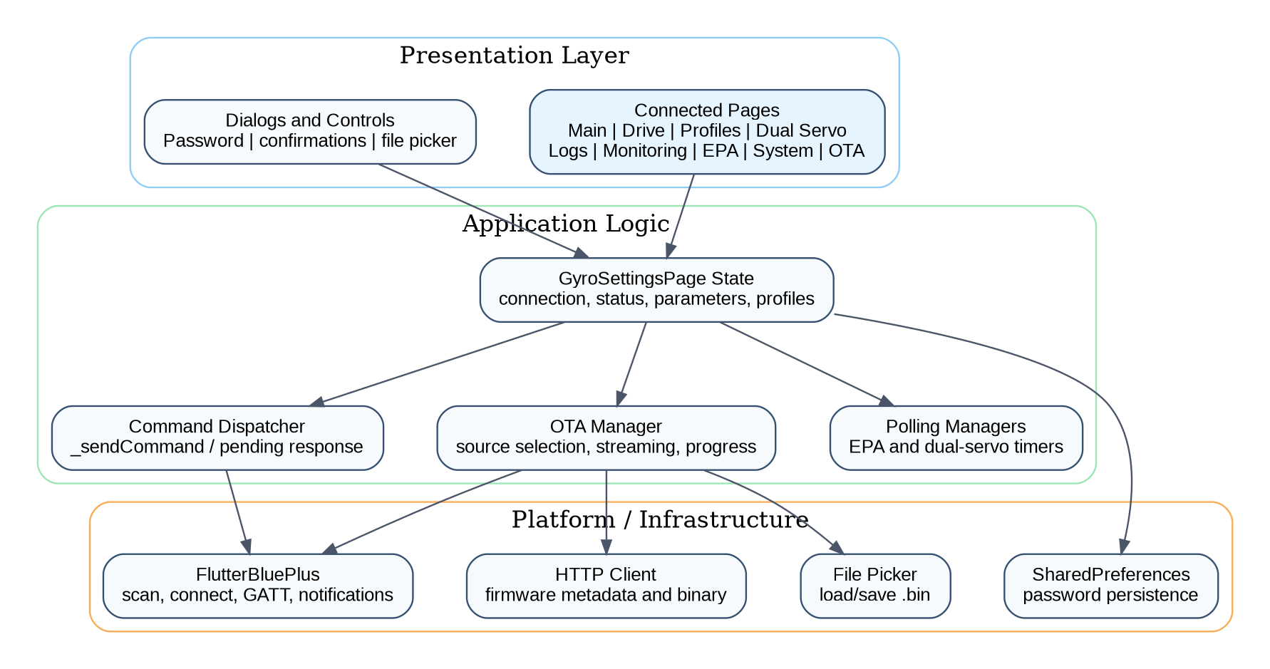
Figure 2. Logical layers and major application components.
11.3 BLE GATT Service Layout
Control traffic and bulk firmware traffic are separated. Settings RX carries application commands, Settings TX provides asynchronous notifications and replies, OTA Control manages the update transaction, and OTA Data transports raw binary chunks.
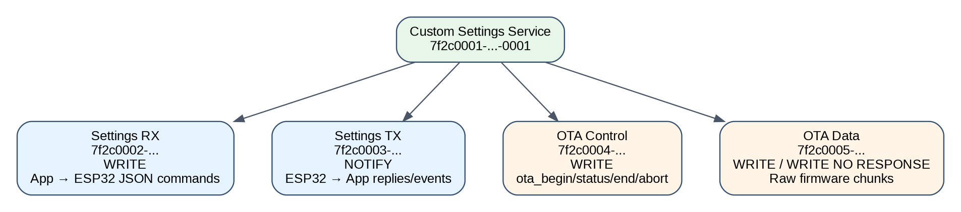
Figure 3. Custom BLE service and characteristic responsibilities.
11.4 Connection and Authentication Sequence
The application includes extra waits and retries because platform APIs may report connect completion before GATT operations are fully ready. After authentication, the application requests the core data sets required to build the connected UI.
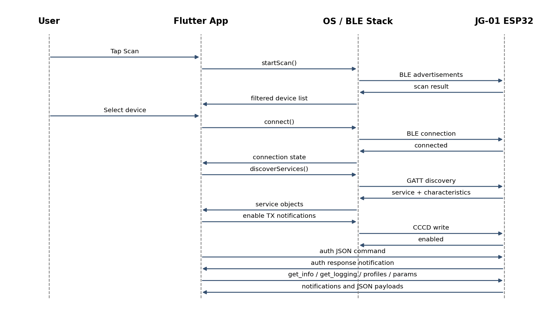
Figure 4. BLE scan, connection, service discovery, authentication, and initial synchronization.
11.5 Command Request/Response Sequence
Commands that require acknowledgement allocate a Completer. Incoming TX notifications are parsed and matched to the currently pending command. A timeout prevents an indefinitely blocked user action.
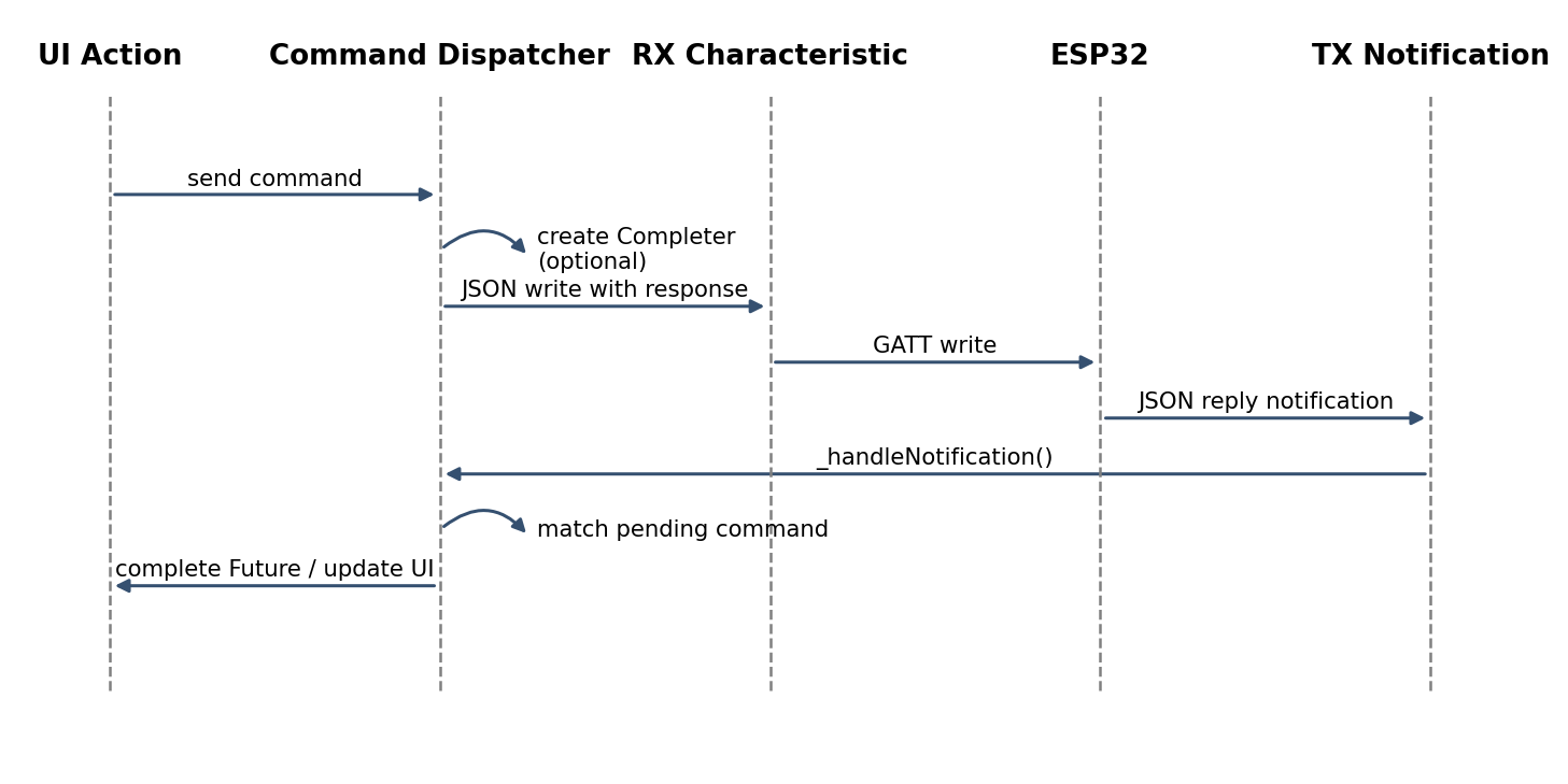
Figure 5. Normal JSON command lifecycle.
11.6 BLE OTA Transaction
The application verifies the selected or downloaded firmware, starts an OTA transaction, streams the binary with platform-aware pacing, finalizes the image, and expects the target device to reboot. Errors trigger an abort request whenever possible.
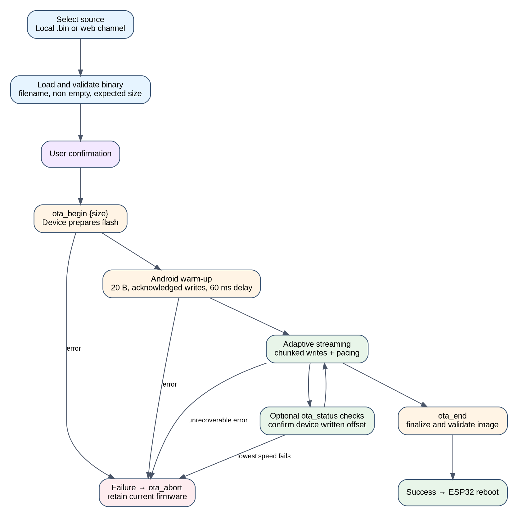
Figure 6. End-to-end firmware update process.
11.7 Adaptive OTA Speed State Machine
Average write latency and write failures move the sender toward a safer level. Sustained low latency can move it back toward faster levels. Android currently uses a deliberately conservative single level plus a slow warm-up phase.

Figure 7. Transfer-rate adaptation used by the Windows implementation.
11.8 Application State and Parameter Data Flow
Notifications update the in-memory maps that drive the UI. User modifications are staged in _dirtyParams and sent individually only when Save is selected. The device parameter list is refreshed after successful writes.

Figure 8. Runtime state synchronization and changed-parameter handling.
11.9 Diagram-to-Code Mapping
| Concern | Primary implementation | Purpose |
| Application root | JasaGyroApp / GyroSettingsPage | Theme, localization, and connected application state. |
| BLE scanning | _startScan() and scanResults subscription | Find and filter compatible devices. |
| Connection setup | _connect(), _waitUntilConnected(), _discoverServicesWhenConnected() | Create a stable GATT session and resolve characteristics. |
| Authentication | _authenticateDevice() | Authenticate and persist a working password per advertised device name. |
| Commands | _sendCommand() | Encode JSON, write RX, optionally wait for a matched response. |
| Incoming data | TX notification subscription and notification handler | Assemble chunks, parse JSON, update application state. |
| OTA control | _sendOtaControlCommand() | Serialize transactional OTA control commands. |
| OTA stream | _startBleOtaUpdate() | Stream firmware with pacing, warm-up, progress, and fallback. |
| OTA adaptation | _OtaAdaptiveSpeed / _OtaSpeedLevel | Select chunk size and delay based on platform and observed latency. |
| Firmware distribution | _checkWebFirmwareUpdate() | Check release channel, compare versions, download and validate binary. |
| Parameter persistence | _saveChanges() | Write only modified settings and refresh the authoritative list. |
| Live configuration | EPA and dual-servo polling timers | Maintain near-real-time configuration feedback while a page is active. |
12. Application Functions and Configuration Workflows
This section documents the user-visible menu structure and the detailed runtime behavior of parameter handling, EPA calibration, and dual-servo configuration. The descriptions follow the application source code and distinguish temporary live changes from values explicitly saved to non-volatile device storage.
12.1 Main Menu Items
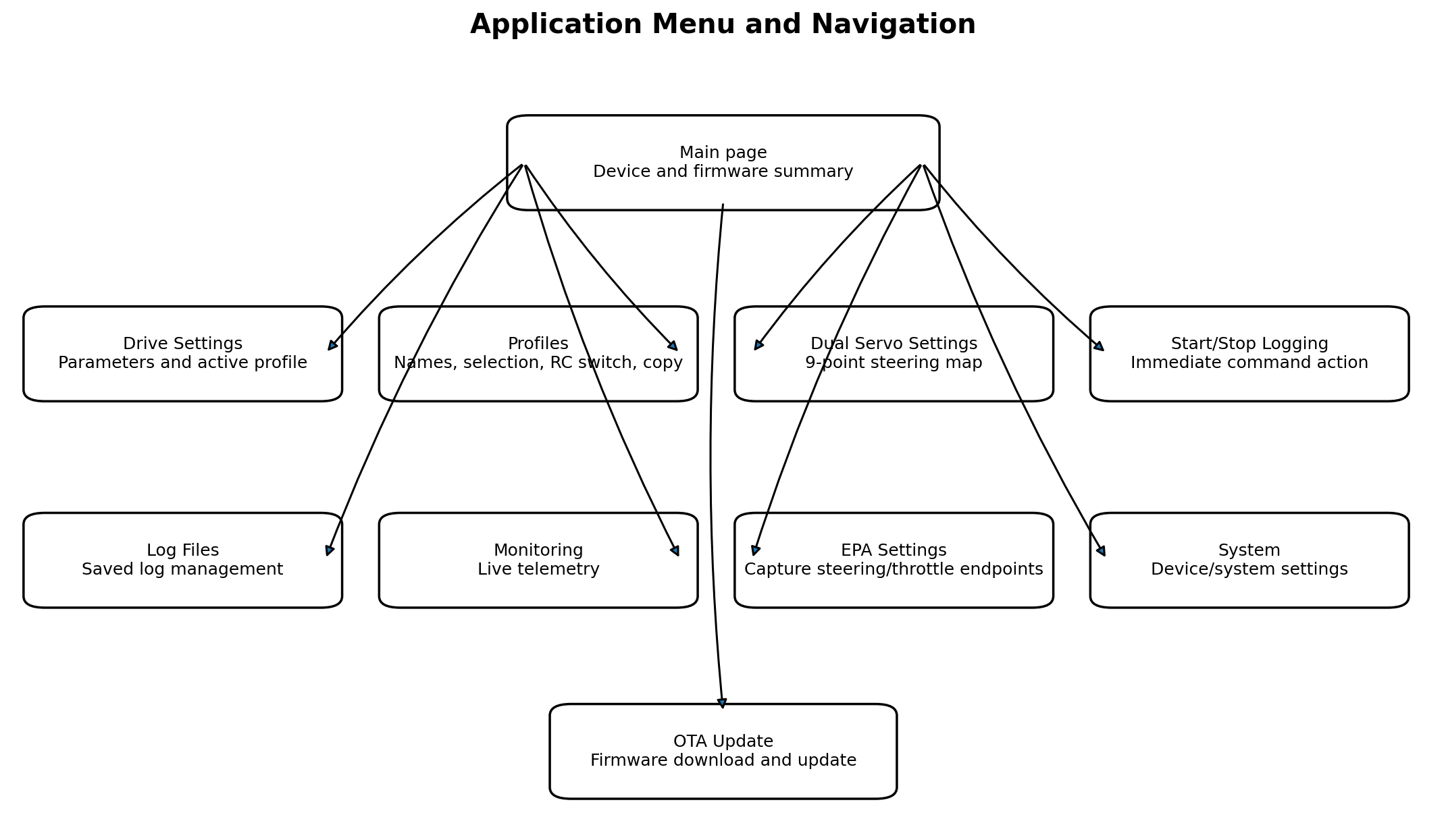
Figure 12-1. Main-page menu and navigation destinations.
| Menu item | Destination / action | Primary purpose | Implementation status in this file |
| Drive Settings | ConnectedPage.driveSettings | View device information, select active profile, edit gyro/control parameters, and save modified values. | Implemented |
| Profiles | ConnectedPage.profiles | Rename profiles, load an active profile, configure an RC/iBus secondary-profile switch, and copy the active profile. | Implemented |
| Dual Servo Settings | ConnectedPage.dualServoSettings | Configure a nine-point left/right servo output map, reverse options, live testing, and persistent save. | Implemented |
| Start/Stop Logging | Immediate start_logging or stop_logging command | Toggle logging without opening another page. Icon and description reflect current logging state. | Implemented |
| Log Files | ConnectedPage.logFiles | Browse and manage saved log files. | Page route present; detailed behavior depends on the remaining code/device protocol |
| Monitoring | ConnectedPage.monitoring | Display live telemetry and operating values. | Page route present; detailed behavior depends on the remaining code |
| EPA Settings | ConnectedPage.epaSettings | Capture steering and throttle low, center, and high pulse widths and save them. | Implemented |
| System | ConnectedPage.system | System-level configuration and information. | Page route present |
| OTA Update | ConnectedPage.otaUpdate | Check, download, select, and install firmware through BLE or prepare a file for Wi-Fi OTA. | Implemented |
Navigation safety behavior:
The app bar shows a Back button whenever the current page is not the main page.
Leaving EPA Settings stops the 500 ms poll timer and sends exit_epa.
Leaving Dual Servo Settings stops its poll timer and sends dual_servo_center so a test position is not left active.
Disconnecting performs the same cleanup before BLE subscriptions and characteristics are cleared.
Refresh is disabled while the app is busy or unsaved parameter changes exist, preventing accidental replacement of edited values.
12.2 Parameter Read and Set Operation
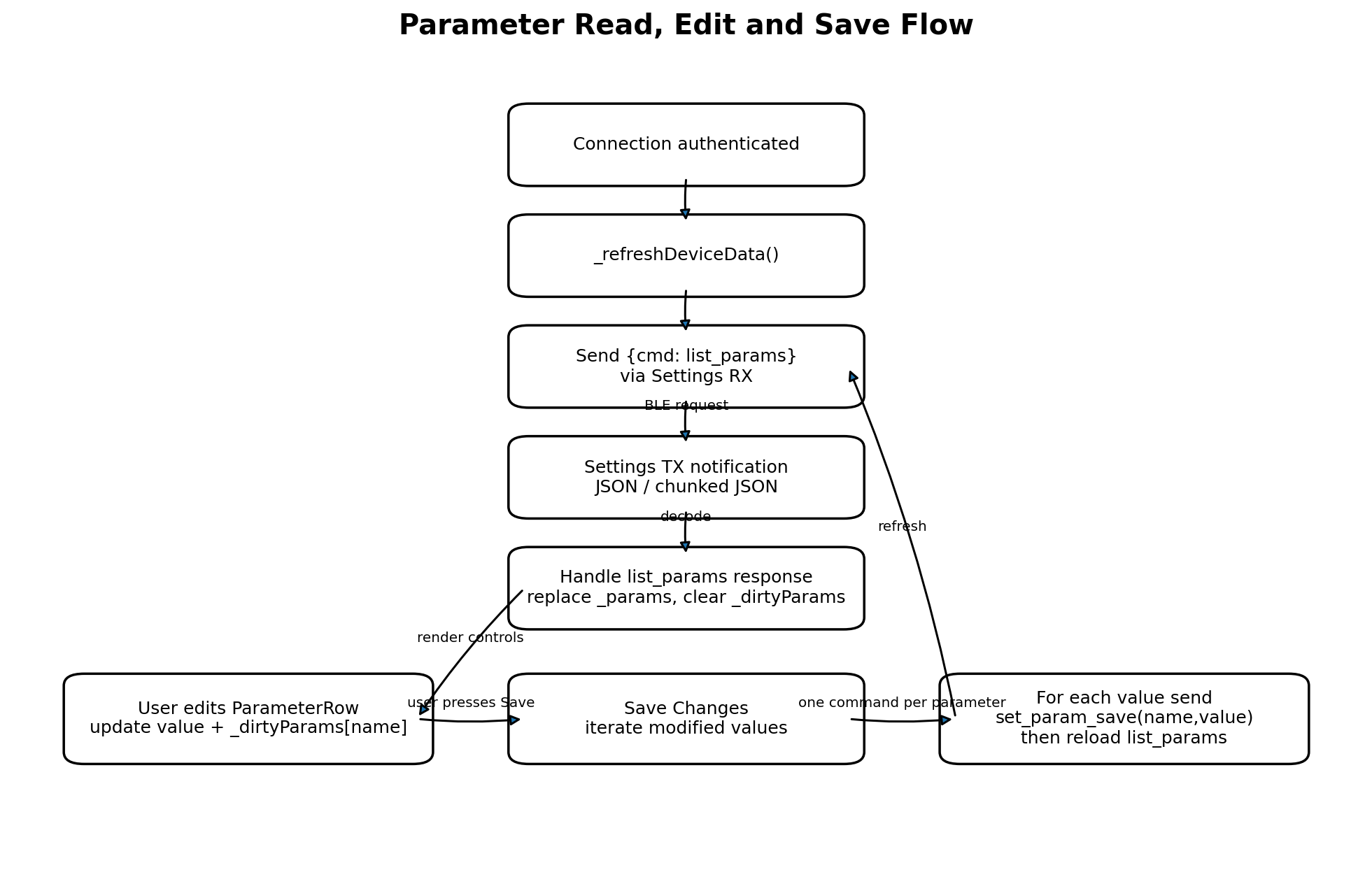
Figure 12-2. Parameter acquisition, local editing, and persistent save sequence.
12.2.1 Reading parameters
After authentication, _refreshDeviceData() sends get_info, get_logging, get_profileinfo, and finally list_params, with short delays between commands.
list_params is sent as JSON through the Settings RX characteristic. The device response arrives through the Settings TX notification characteristic.
A response may be a complete JSON message or a series of messages whose type is chunk. Chunk sequence 0 clears the assembly buffer; each data fragment is appended until last=true.
When cmd=list_params is decoded successfully, the app clears _dirtyParams, replaces _params with the returned params array, and updates the status with the number of loaded parameters.
The Drive Settings page sorts known parameters into a preferred engineering order and renders each entry through _ParameterRow. The parameter metadata supplied by the device determines the appropriate editor and displayed value.
12.2.2 Local editing and dirty-state tracking
Changing a control immediately updates the value field in the corresponding local _params entry.
The same value is copied into _dirtyParams using the parameter name as the key. This map therefore contains only values changed by the user since the last successful parameter load.
Rows whose names occur in _dirtyParams are rendered as modified. Profile changes and refresh actions are disabled while dirty values exist, preventing silent loss of edits.
Editing a parameter does not immediately write it to the gyro. The change remains local until Save Changes is pressed.
12.2.3 Saving parameters
The save function copies _dirtyParams to a temporary map so the iteration is stable even if UI state later changes.
For every changed entry it sends {cmd: set_param_save, name: <parameter>, value: <value>} and waits for the matching response.
Only one command may wait for a response at a time. _pendingResponse and _pendingResponseCmd correlate the reply, and the normal timeout is 10 seconds.
The progress status is updated after each saved parameter.
After all individual writes complete, list_params is requested again. The returned authoritative values replace the local list and clear the dirty map.
A device response with ok=false becomes an exception and is shown as a save error. Successfully completed earlier parameters may already have been persisted, so a subsequent refresh is useful after resolving the error.
| Command | Direction | Important fields | Application effect |
| list_params | App → device | cmd | Device returns params array; app replaces _params and clears _dirtyParams. |
| set_param_save | App → device | cmd, name, value | Writes one changed parameter and waits for confirmation. |
| load_profile | App → device | cmd, profile | Changes active profile; local parameter list is cleared and then reloaded. |
| get_profileinfo | App → device | cmd | Returns profile names, active/secondary profile, and switch channel. |
12.3 EPA Settings Operation
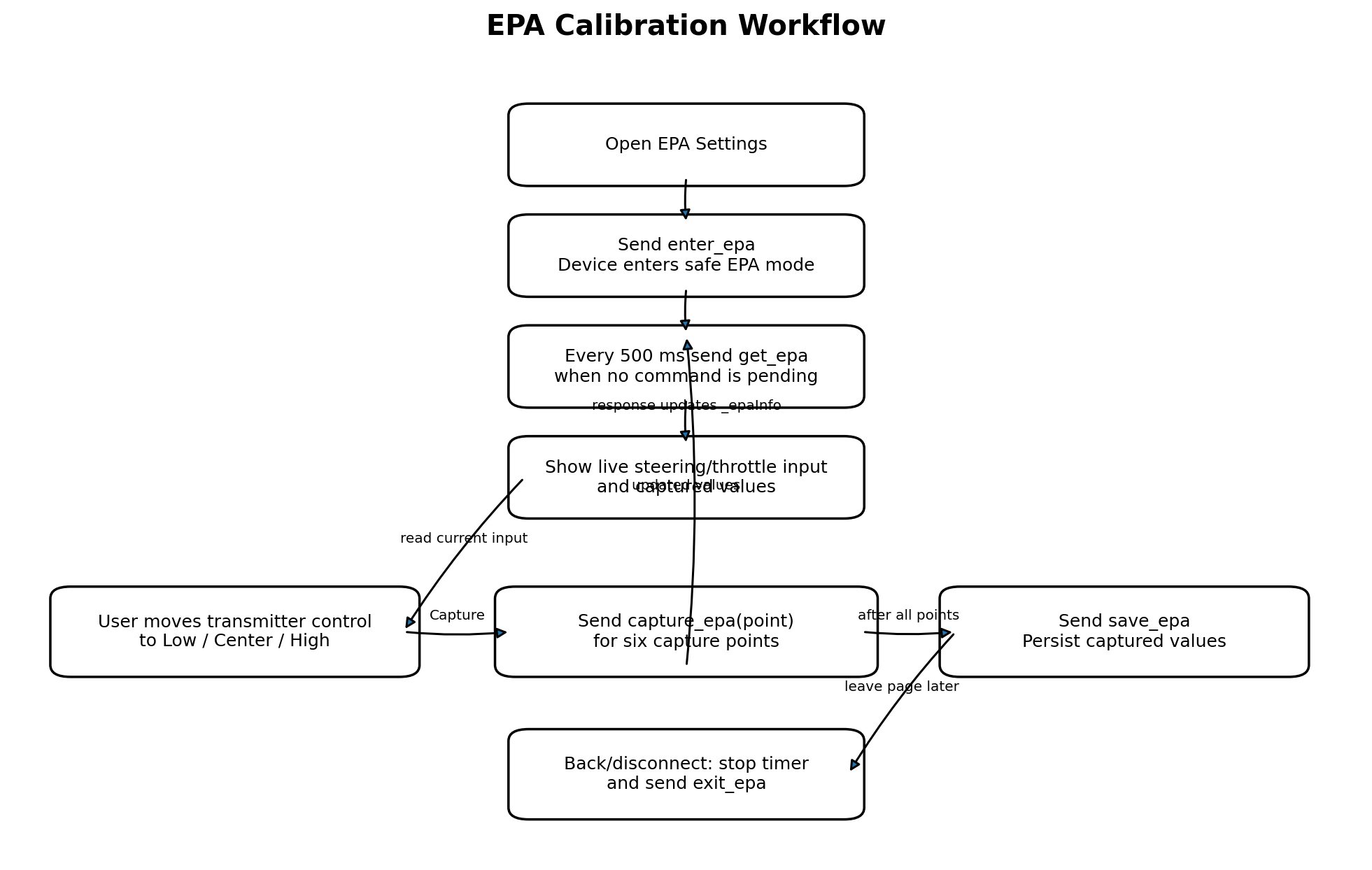
Figure 12-3. EPA mode entry, live polling, point capture, save, and cleanup.
12.3.1 Purpose and displayed values
EPA (end-point adjustment) calibration records the receiver pulse widths representing the low, center, and high positions for steering and throttle. The page displays live steering input, live throttle input, EPA-mode state, and six stored capture values in microseconds:
| Control | Displayed key | Capture point sent to device |
| Steering low | epa_low | low |
| Steering center | epa_center | center |
| Steering high | epa_high | high |
| Throttle low | epa_t_low | t_low |
| Throttle center | epa_t_center | t_center |
| Throttle high | epa_t_high | t_high |
12.3.2 Runtime sequence
Opening the page first changes the UI route to epaSettings and then sends enter_epa. The application sets _isEpaMode and starts polling only after a successful response.
A periodic timer runs every 500 ms. It sends get_epa quietly only while BLE is connected, the EPA page remains open, and no other command is waiting for a response.
Each EPA response replaces _epaInfo. The UI accepts several alternate names for the live steering/throttle fields, making it tolerant of protocol naming variants.
The operator moves the steering wheel or throttle trigger to the desired physical position and presses Capture. The app sends capture_epa with one of the six point identifiers.
The device response contains the updated captured values; the app replaces _epaInfo and displays the new pulse width.
Save EPA Values sends save_epa and waits for confirmation. This is the explicit persistence step.
Returning to the main page, switching away through applicable navigation, or disconnecting stops polling and sends exit_epa. This is important because EPA mode may disable or alter normal control processing on the device.
12.3.3 Operator procedure
Open EPA Settings and verify EPA Mode shows On.
Leave transmitter trims/sub-trims and radio configuration in the intended final state.
Move steering fully left and capture Steering Low; release to neutral and capture Steering Center; move fully right and capture Steering High.
Move throttle to its low/brake endpoint, neutral, and high/forward endpoint, capturing the corresponding three values.
Check that values are plausible RC pulse widths and that low < center < high for non-reversed channels. A reversed channel may appear in the opposite order depending on firmware conventions.
Press Save EPA Values, wait for confirmation, then leave the page normally so exit_epa is sent.
12.4 Dual Servo Settings Operation
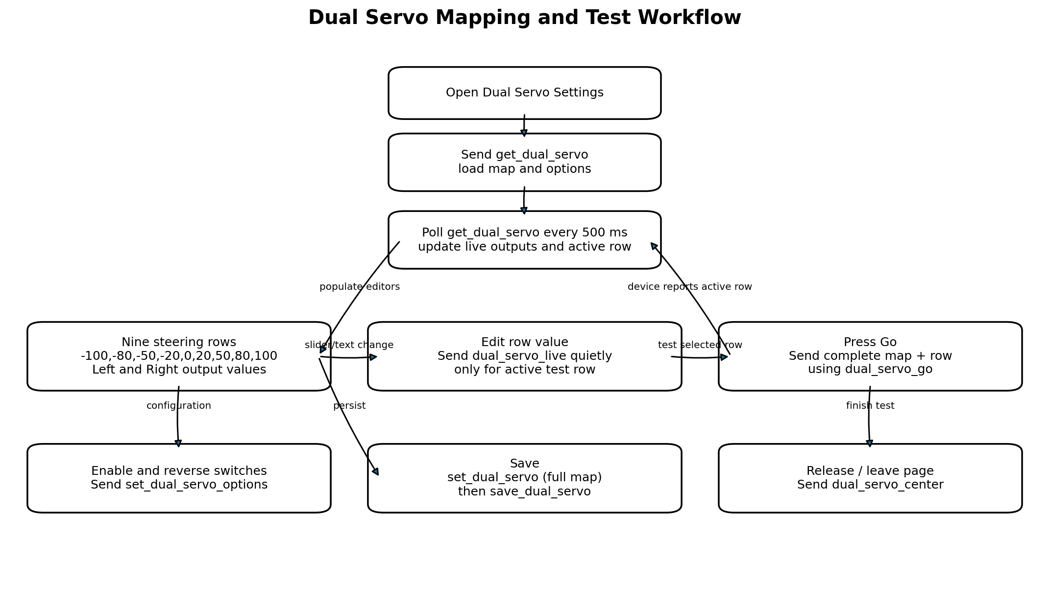
Figure 12-4. Dual-servo map loading, live testing, option updates, save, and centering.
12.4.1 Steering-map model
The configuration is a nine-point transfer map. Each row represents one normalized steering-input location, and each row stores independent output values for servo 1 (left column) and servo 2 (right column). The default input grid is:
-100, -80, -50, -20, 0, 20, 50, 80, 100
The map allows nonlinear output curves, different left/right steering amounts, electronic Ackermann adjustment, center matching, and compensation for asymmetric linkages.
The header displays live steering input, servo 1 output, servo 2 output, active test row, and a graphical wheel visualization.
The enable switch and three reverse options are separate from the nine-point map but are included when full-map commands are sent.
12.4.2 Loading and polling
Opening the page sends get_dual_servo and waits for the initial configuration.
A 500 ms timer then sends get_dual_servo quietly whenever no other response is pending.
Responses update _dualServoInfo, enable/reverse flags, left/right arrays, live outputs, and _dualServoActiveRow.
Immediately after the user changes an option, poll responses are temporarily ignored using _ignoreDualServoPollUntil. This prevents an older periodic response from visually undoing the user’s new switch state before the option command completes.
12.4.3 Row testing and live adjustment
Each of the nine editors contains the input-row value, servo 1 value, servo 2 value, an active indicator, and a Go action.
Pressing Go builds a dual_servo_go command containing the complete nine-point map, all enable/reverse options, the selected row index, and that row’s left/right values. The device can then drive the servos to the requested test position.
While that same row is active, changing its left or right value sends dual_servo_live quietly. This allows immediate mechanical adjustment without repeatedly pressing Go.
dual_servo_live is suppressed when another response is pending or when the edited row is not the active test row.
Pressing Release / Center sends dual_servo_center. Leaving the page or disconnecting also sends this command automatically.
12.4.4 Enable and reverse options
Dual-servo enable, steering-input reverse, servo 1 reverse, and servo 2 reverse are transmitted immediately with set_dual_servo_options.
The app waits briefly for any pending poll response to finish before sending the option command, avoiding the single-pending-response restriction.
A short ignore window remains after completion so the UI is not overwritten by a stale get_dual_servo notification.
12.4.5 Saving
Save first sends set_dual_servo with the complete nine-point left/right map and all option flags.
After the device confirms the full map, the app sends save_dual_servo. This second command is the explicit persistent-storage operation.
Temporary Go and Live commands are intended for testing; they should not be treated as proof that settings are stored across reboot until save_dual_servo succeeds.
| Command | When sent | Payload summary | Persistent? |
| get_dual_servo | Page open and every 500 ms | Requests map, flags, live input/output, active row | No |
| set_dual_servo_options | Enable/reverse switch changed | enabled, steer_reverse, servo1_reverse, servo2_reverse | Depends on device; final Save still recommended |
| dual_servo_go | Go pressed on a row | Full map, flags, row, selected left/right | No; test action |
| dual_servo_live | Active row value edited | row, left, right, flags | No; live test action |
| set_dual_servo | Save pressed | Full nine-point map and flags | Stages/applies full configuration |
| save_dual_servo | After set_dual_servo succeeds | cmd only | Yes |
| dual_servo_center | Release, leave page, disconnect | cmd only | No; safety/centering action |
12.5 Concurrency, Response Matching, and Failure Handling
The command layer permits only one response-waiting command at a time. A second waitForResponse command throws an error if _pendingResponse is occupied.
Replies are matched by the cmd field. A notification completes the pending Future only when its command equals _pendingResponseCmd.
EPA and dual-servo periodic polls skip their cycle when another command is pending. This reduces command overlap and response ambiguity.
Quiet polling and live-update commands avoid constantly replacing the user-facing status text, while explicit operations such as Save, Capture, Go, and Center report success or failure.
All decoded responses with ok=false are surfaced as application errors. Invalid JSON and incomplete chunk assembly are also reported.
On disconnect, pending work is completed with an error, timers and subscriptions are cancelled, characteristics are cleared, and cached UI state is reset.